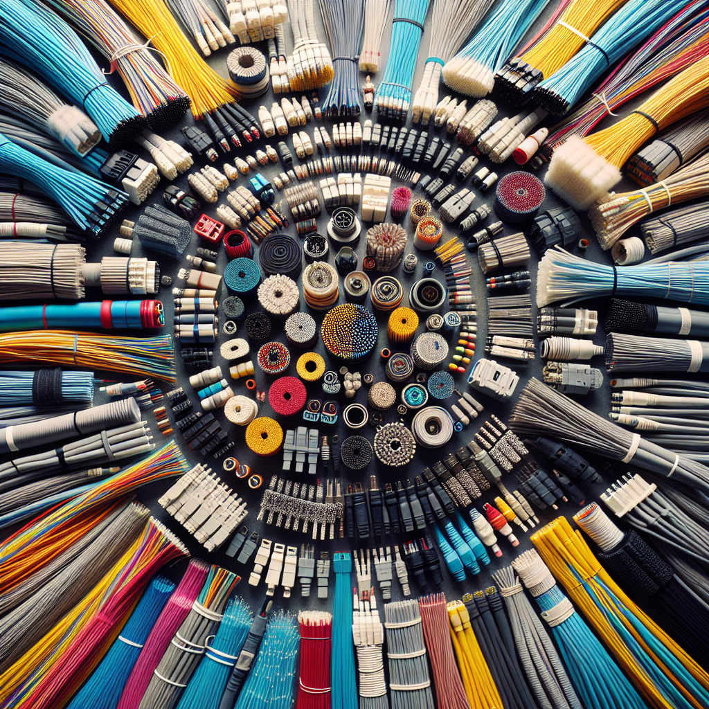
Fiber optic network installation diagrams may seem like a daunting technical puzzle to unravel, but fear not – we are here to demystify the complexities for you! In this introduction, we will delve into the intricacies of fiber optic network installation diagrams, shedding light on the essential components and processes involved in setting up a high-speed internet and reliable communication network. From understanding the different types of diagrams to deciphering the symbols and measurements used, we will take you on a journey through the world of fiber optics, making it easier for you to visualize and implement your own network infrastructure. Let’s dive in and unravel the mysteries together!
Understanding Fiber Optic Networks
Fiber optic networks utilize optical fibers to transmit data through pulses of light. These networks are widely recognized for their ability to provide high-speed and reliable communication connections. Some key points to consider when understanding fiber optic networks include:
- Definition and Basics of Fiber Optic Networks
Fiber optic networks consist of thin strands of glass or plastic fibers that carry information in the form of light signals. These fibers are capable of transmitting data over long distances without significant loss of signal strength. The basic principle behind fiber optics involves the transmission of light through total internal reflection within the fiber core. - Benefits of Fiber Optic Networks
Fiber optic networks offer numerous advantages over traditional copper wire networks. These benefits include higher bandwidth capacity, faster data transmission speeds, increased reliability, and immunity to electromagnetic interference. Additionally, fiber optic networks are more secure and less prone to signal degradation over long distances compared to copper cables. - Importance of Proper Installation Diagrams
Proper installation diagrams are essential for the successful deployment and maintenance of fiber optic networks. These diagrams provide detailed instructions on how to connect fiber optic components, including cables, connectors, splices, and terminations. By following accurate installation diagrams, network technicians can ensure the efficient operation of the fiber optic network and minimize the risk of signal loss or downtime.
Components of Fiber Optic Network Installation Diagrams

Main Components
- Fiber Optic Cables
- Fiber optic cables are the backbone of any fiber optic network installation diagram, transmitting data using light signals.
- These cables consist of a core where the light travels, surrounded by cladding that reflects the light back into the core.
- Common types include single-mode fibers for long-distance transmission and multi-mode fibers for shorter distances.
- Fiber optic cables are known for their high bandwidth, low attenuation, and resistance to electromagnetic interference.
- Connectors and Splices
- Connectors are used to join individual fiber optic cables together, allowing for seamless data transmission.
- Common connector types include SC, LC, and ST connectors, each with specific applications and characteristics.
- Splices, on the other hand, are used to permanently join two fiber optic cables together without connectors.
- Proper alignment and fusion of fibers are crucial in splicing to minimize signal loss and maintain network performance.
- Patch Panels
- Patch panels serve as central hubs where fiber optic cables from different network components are connected and managed.
- These panels provide a convenient way to organize and route fibers, making network maintenance and troubleshooting easier.
- Patch panels come in various configurations, such as rack-mounted or wall-mounted, to suit different installation requirements.
- Labeling and documentation of connections on patch panels are essential for efficient network management and future upgrades.
- Transceivers
- Transceivers, also known as fiber optic transceivers, are essential components that convert electrical signals into optical signals for transmission over fiber optic cables.
- These devices enable seamless integration of fiber optic networks with existing copper-based network infrastructure.
- Transceivers come in different form factors, such as SFP, SFP+, and QSFP, each with specific data rate and connectivity options.
- Compatibility between transceivers and network equipment is crucial for ensuring reliable data transmission and network performance.
Supporting Components
f Fiber Optic Network Installation Diagrams
- Racks and Enclosures
Fiber optic network installation diagrams typically include detailed plans for racks and enclosures. Racks provide a structured framework for mounting various components such as servers, switches, and patch panels. Enclosures, on the other hand, offer protection and security for sensitive equipment. The diagrams outline the placement of racks and enclosures in relation to the overall network layout, ensuring efficient organization and accessibility.
- Power Supply Units
Power supply units are essential components in fiber optic network installations as they provide the necessary electrical power to run the network equipment. The diagrams specify the location of power supply units within the network infrastructure, ensuring proper distribution of power to all connected devices. Additionally, the diagrams outline backup power solutions, such as uninterruptible power supply (UPS) systems, to ensure continuous operation in case of power outages.
- Cable Management Systems
Effective cable management is crucial in fiber optic network installations to maintain signal integrity and prevent signal interference. The diagrams detail the implementation of cable management systems, including cable trays, racks, and sleeves, to organize and protect the network cables. By following the cable management guidelines outlined in the diagrams, technicians can ensure a tidy and efficient network infrastructure that facilitates troubleshooting and maintenance tasks.

Types of Fiber Optic Network Installation Diagrams
Schematic Diagrams
Types of Fiber Optic Network Installation Diagrams
Schematic diagrams in fiber optic network installations serve as detailed visual representations of the system’s components and connections. These diagrams are essential tools for understanding the layout and configuration of the network infrastructure. They provide a high-level overview of how various elements are interconnected within the system, offering a clear and concise depiction of the network’s architecture.
Overview and Purpose
Schematic diagrams act as blueprints for fiber optic network installations, outlining the placement of key components such as fiber optic cables, connectors, splices, and termination points. They showcase the physical arrangement of these elements in a structured format, allowing technicians and engineers to grasp the system’s design at a glance. The primary purpose of these diagrams is to facilitate the planning, implementation, and maintenance of fiber optic networks by presenting a visual roadmap of the entire network setup.
Representation of Components and Connections
In schematic diagrams, components of the fiber optic network are symbolized using standardized icons and labels to indicate their specific functions and locations. The connections between these components are illustrated through lines or arrows, showing the pathways through which data signals travel within the network. By accurately depicting the relationships among different parts of the network, these diagrams enable technicians to troubleshoot issues, make necessary adjustments, and expand the network infrastructure with precision and efficiency.
Physical Layout Diagrams
Physical layout diagrams in fiber optic network installation provide a detailed spatial arrangement of the network components. These diagrams outline the exact placement of fiber optic cables, equipment, and connections within the network infrastructure.
Key aspects of Physical Layout Diagrams include:
– Spatial Arrangement: These diagrams depict the physical location of fiber optic cables, equipment racks, patch panels, and other network components. They illustrate how these elements are interconnected and positioned within the network environment.
- Cable Routing and Management: Physical layout diagrams also showcase the routing of fiber optic cables throughout the network. They highlight the paths taken by the cables from the point of entry into the building to their termination points. Additionally, these diagrams detail how cables are managed, organized, and secured to ensure efficient network operation and maintenance.
Designing Fiber Optic Network Installation Diagrams
Planning Stage
Designing Fiber Optic Network Installation Diagrams
- Assessment of Network Requirements
The planning stage of designing fiber optic network installation diagrams begins with a thorough assessment of the network requirements. This involves understanding the specific needs of the network, such as the expected data transmission speeds, the volume of data to be transmitted, the distance the data needs to travel, and any special considerations for the network’s intended use. By conducting a detailed assessment, network designers can determine the type and quantity of fiber optic cables needed, as well as the appropriate equipment and components required for efficient network operation.
- Determining Cable Routes and Connections
Another crucial aspect of the planning stage is determining the cable routes and connections within the network. This involves mapping out the physical pathways that the fiber optic cables will follow, taking into account factors such as the layout of the building or area where the network will be installed, potential obstructions or interferences, and the need for cable protection and management. Additionally, identifying the optimal locations for network connections, such as fiber optic splices and terminations, is essential to ensure seamless data transmission and easy maintenance of the network in the future.
Software Tools for Diagram Creation
When it comes to designing fiber optic network installation diagrams, using specialized software tools is crucial for ensuring accuracy and efficiency in the planning and implementation process. These tools are specifically tailored to handle the technical requirements of fiber optic networks, allowing for precise depiction of the network layout and components.
Importance of Using Specialized Software:
- Precision: Specialized software tools offer the precision required to accurately represent the intricate details of fiber optic network installations, including cable runs, connection points, and equipment placement.
- Efficiency: By utilizing software designed for fiber optic network diagrams, engineers and technicians can streamline the design process, reducing the likelihood of errors and saving time during implementation.
- Compatibility: These tools are often compatible with industry-standard formats and protocols, ensuring seamless integration with other network design and management systems.
- Visualization: Specialized software provides advanced visualization capabilities, allowing stakeholders to easily understand and interpret the network layout, making it simpler to identify potential issues or optimizations.
Popular Diagramming Tools in the Industry:
- AutoCAD: Widely used in the telecommunications industry, AutoCAD offers robust features for creating detailed fiber optic network diagrams, including 3D modeling capabilities for visualizing complex installations.
- Visio: A popular choice for network diagramming, Visio provides a user-friendly interface and a wide range of templates specifically tailored for designing fiber optic networks.
- Lucidchart: Known for its collaborative features, Lucidchart enables multiple team members to work on network diagrams simultaneously, making it ideal for large-scale fiber optic installations.

- FiberPlanIT: A specialized tool for fiber optic network planning, FiberPlanIT offers automated design capabilities based on industry best practices, helping to optimize network performance and reliability.
Implementing Fiber Optic Network Installation Diagrams
Installation Process Overview
mplementing Fiber Optic Network Installation Diagrams
The installation process of fiber optic network diagrams involves several crucial steps to ensure a seamless and efficient setup. Each stage plays a vital role in the successful implementation of the network infrastructure. Here is a detailed overview of the installation process:
- Preparing the Site
- Before commencing the installation, it is essential to conduct a thorough site survey to assess the environment and identify any potential obstacles or challenges.
- Clearing the designated area of any debris or obstructions is necessary to provide a safe and accessible workspace for the installation team.
- Ensuring that all necessary tools and equipment are readily available will help streamline the installation process and prevent delays.
- Installing and Connecting Fiber Optic Components
- The next step involves installing the fiber optic cables, connectors, and other essential components according to the network diagram specifications.
- Careful attention must be paid to the routing of the cables to minimize signal loss and interference.
- Properly connecting the fiber optic components using splicing or termination techniques is critical to establishing reliable and high-performance network connections.
- Testing and Troubleshooting
- Once the installation is complete, thorough testing of the network is essential to ensure that all connections are secure and functioning correctly.
- Utilizing advanced testing equipment such as optical time-domain reflectometers (OTDR) can help identify any potential issues or signal loss within the network.
- In case of any discrepancies or performance issues, prompt troubleshooting and corrective actions should be taken to rectify the problems and optimize network performance.
Best Practices for Efficient Installation
Fiber optic network installation diagrams serve as crucial blueprints for ensuring a seamless implementation process. To maximize efficiency during installation, adhering to best practices is essential:
- Labeling and Documentation:
- Properly labeling all components, cables, and connections according to the diagram helps in accurate installation and troubleshooting.
- Maintaining detailed documentation of the installation process ensures clarity for future maintenance or upgrades.
- Safety Protocols and Regulations:
- Adhering to safety protocols, such as wearing appropriate protective gear and following industry standards, minimizes the risk of accidents during installation.
- Compliance with regulations regarding fiber optic installation ensures the network’s reliability and longevity.
- Post-Installation Maintenance and Monitoring:
- Implementing a robust maintenance plan post-installation, including regular inspections and cleaning schedules, enhances the network’s performance and lifespan.
- Continuous monitoring of the network’s performance using diagnostic tools and software enables prompt identification and resolution of any issues.
FAQs: Fiber Optic Network Installation Diagrams: Demystifying the Technicalities
What is a fiber optic network installation diagram?
A fiber optic network installation diagram is a visual representation of how fiber optic cables are installed within a network infrastructure. It illustrates the connections between various components, such as optical fibers, connectors, splice points, and network devices, to ensure a well-organized and efficient network layout.
Why is a fiber optic network installation diagram important?
A fiber optic network installation diagram is essential for planning, implementing, and maintaining a fiber optic network. It helps network technicians and engineers understand the network design, identify potential issues or bottlenecks, and facilitate troubleshooting and upgrades. Having a detailed diagram can also improve communication among team members and ensure consistency in network configurations.
What information should be included in a fiber optic network installation diagram?
A fiber optic network installation diagram should include details such as the location of fiber optic cables, the type and specifications of optical fibers used, the connectors and splice points, the routing of cables, and the connections to network devices. It should also indicate any relevant distances, signal strengths, and potential points of failure to aid in network maintenance and troubleshooting.
How can I create a fiber optic network installation diagram?
To create a fiber optic network installation diagram, you can use specialized network diagramming software that allows you to drag and drop components, connectors, and labels to build a detailed illustration. You can also use tools such as Visio or AutoCAD to create custom diagrams based on your network design. It is important to follow industry standards and best practices when designing your diagram to ensure accuracy and reliability.


